Cool Stuff!

How I Built a Motorized Lighting Shutter from an Old 3D Printer
March 4, 2026
Introduction
Recently, I decided to take on the task of creating a custom lighting special for the production I am currently working on: Crabs in a Bucket by Bernardo Cubría.
There is a moment in the play where a lid is placed over the set (in our case, a scaled-up interior of a Home Depot bucket). I wanted to replicate this effect using light by creating a vertical shutter that would close across our black box theater.
Early Experiments
I experimented with a few different ways of accomplishing this effect, including remotely controlling the built-in shutters on a Source Four and having a crew member manually place an object in front of the light.
Unfortunately, these options were not feasible in my space for a couple of reasons.
My initial plan was to control the shutter using a length of tie line that a crew member could pull from the ground. However, since I still had time before tech week, I decided to see if I could automate the effect using parts I already had on hand.
Inspiration
My first thought was to use my retired Ender 3 V1 3D printer, which I had recently disassembled and put into storage.
Online, I had seen many people repurpose parts from these printers to build devices such as filament dryers and laser engravers, but I had never seen anyone use it in a theatrical environment.
It seemed like these components had a lot of potential for building a motorized shutter system.
Prototyping
I began by grabbing the aluminum extrusions originally used for the printer's gantry and test-fitting them onto a 50-degree Source Four barrel.
The fit was exactly what I was looking for.
From there, I looked around my workspace to see what I could use to mount the system to the end of the barrel. I grabbed a 2x4 and used two 2.5-inch drywall screws through holes at the top of the gantry to clamp it onto the gel slot.
Using tape, foam board, and a little bit of coercion, I managed to assemble a janky but functional prototype that I could demonstrate at the next production meeting.
Designing the Electronics
Once I had a working prototype, it was time to make the device a little less… janky.
I knew I wanted the shutter to be DMX controlled, so I started researching how other DIY lighting fixtures typically handle DMX input.
After a bit of research, I discovered the MAX485, an integrated circuit that allows microcontrollers to receive RS-485 signals (the physical layer used by the DMX standard). I was able to picked up the little brother of the MAX485—the MAX483—at a local electronics store the same day. Unfortunately, this chip didn’t end up working for me, possibly because it is limited to a maximum of 250 kbps, which is the same bitrate used by DMX. That likely left too little tolerance for reliable communication.
Fortunately, after reaching out to my technical director, I was able to borrow an Arduino DMX Hat that already contained a MAX485 transceiver.
Originally, I planned to wire everything directly to the salvaged Creality Ender 3 control board using some of its unused pin headers, but the form factor of the Arduino hat and the approaching tech deadline pushed me toward a different solution.
Instead, I used:
- the Creality board for its built-in stepper motor drivers
- an Arduino Uno with the DMX hat to receive and interpret DMX data
- I²C communication between the two boards to control the motor position
Mounting and More Prototyping
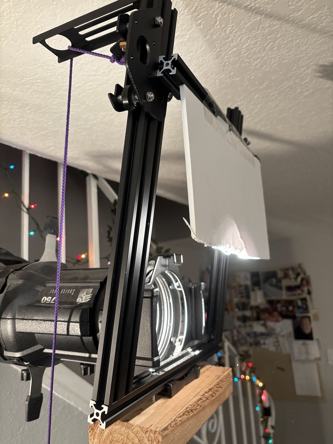
With the electronics mostly figured out, it was time to improve the mechanical design. The first thing to go was the 2×4 prototype mount and the foam board which was acting as the shutter. The foam board would later be replaced with a piece of black painted luan and mounted to the extrusion using M3 machine screws.
I began evaluating all the possible mounting points on the fixture, including the yoke, the focus knob, the accessory slot, and the gel frame slot. I designed and 3D-printed mounts for several of these locations, but ultimately settled on a custom gel frame mount that slides into the gel slot at the front of the fixture.
The frame was printed using PETG filament with a high infill. Since this light will only be on for a few moments at a time, I am not worried about the heat causing the plastic to deform.
This approach made installation quick while still secure since I used the Source Four’s built-in gel frame clip to secure it into the gel frame slot. Of course, an additional safety cable was also attached to the device just in case.
To attach the gantry, I drilled holes into the aluminum extrusion and connected it to the custom gel frame using M5 machine screws.
Assembling the Final Device
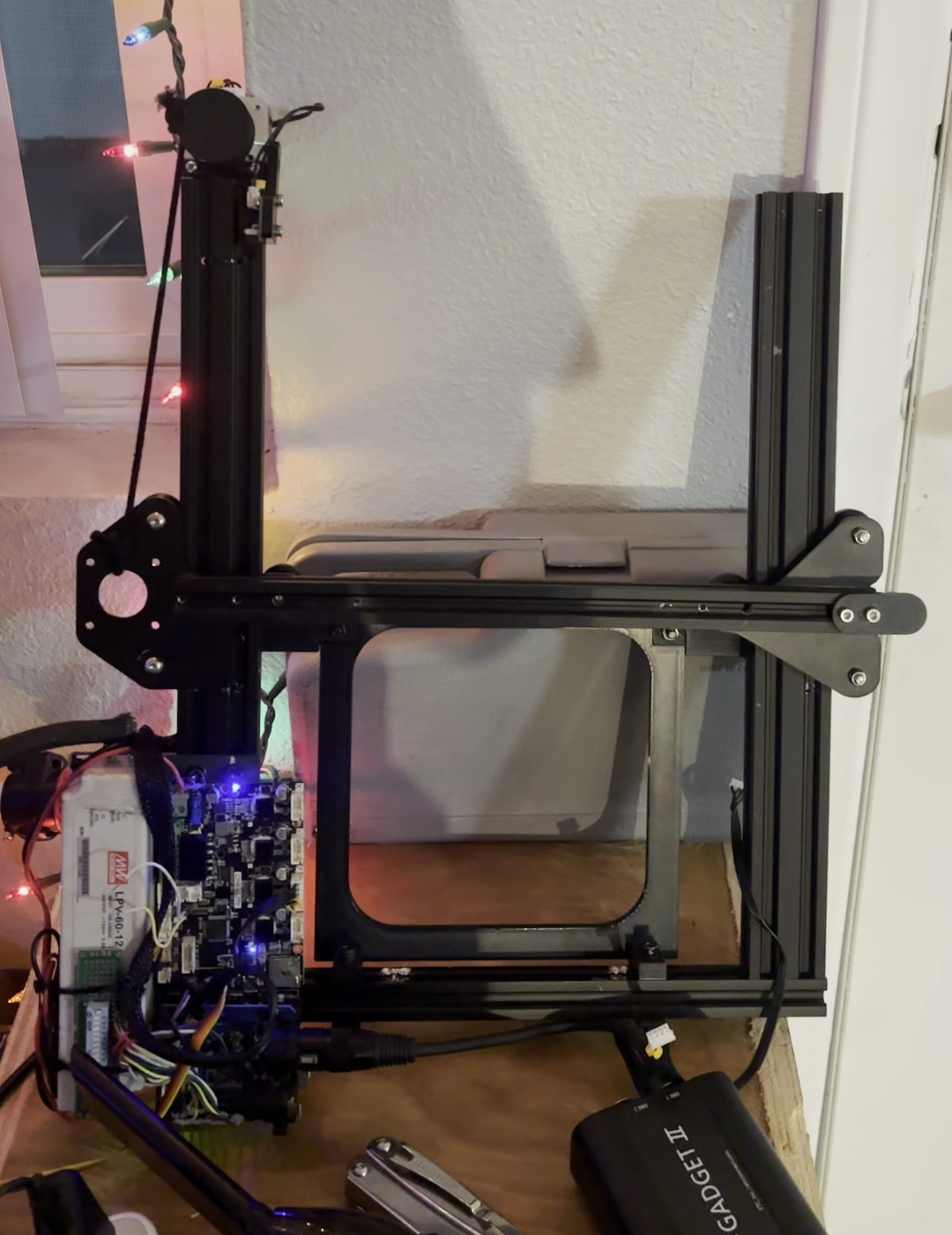
At this point, the device was starting to look much more put together. I mounted one of the Ender 3 stepper motors at the end of the gantry and connected it to the Creality control board using the original wire harness.
Of course, this being a theater project, the shutter mechanism itself is pulled using a length of tie line that winds onto a spool attached to the motor shaft as it turns.
Since I wasn't using the LCD screen normally attached to the Creality board, I was able to repurpose the I²C header for communication with the Arduino.
I also added a small prototype board with a DIP switch, allowing the DMX address to be configured directly on the device without reprogramming the Arduino.
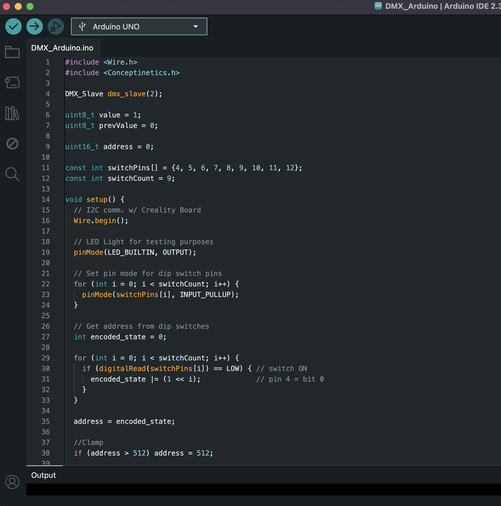
Programming
All of the firmware was written using the Arduino IDE, and the full source code is available here.
The project uses:
- AccelStepper on the Creality board to control the stepper motor
- Conceptinetics on the Arduino to receive DMX data
- Wire for I²C communication between the two microcontrollers
Because the Creality board cannot be programmed directly using the Arduino IDE, I used the STM32duino Arduino Core along with an ST-LINK USB debugger to upload firmware to the board.
After some trial and error, I was able to get everything working reliably.
Testing the Effect
Once everything was assembled, it was time to test the system.When powered on, the shutter first slowly moves upward to find its home position at the top of the gantry. After homing, the device is ready for operation.
From the lighting console, the fixture is patched with a single 8-bit control parameter. As the channel value increases, the stepper motor moves the shutter downward, gradually closing the beam of light across the theater.
Final Thoughts
Success!
I’m really happy with how this project turned out, and I’m excited to use it once we get into tech.
While this may not have been the simplest or most conventional solution, it was a fantastic learning experience and a great test of my skills.
I am really happy that I was able to recycle parts I already had on hand. In the end the only money spent on this project was for additional M3 and M5 screws, as well as the ST-Link which was only a few dollars.
If you have any questions or comments, feel free to reach out via email. Thanks for reading!
Additional photo and videos available here